
9 Investigations
9.1 Corneal Topography and Tomography
9.2 Confocal Microscopy
9.3 Optical Coherence Tomography - Macula
9.4 Optical Coherence Tomography Angiography (OCT-A)
9.5 Optical Coherence Tomography - Glaucoma
9.6 Optical Coherence Tomography – Anterior Segment
9.7 Fundus Autofluorescence Imaging
9.8 Fundus Angiography - Fluorescein
9.9 Fundus Angiography - Indocyanine Green
9.10 B-scan Ultrasonography & UBM
9.11 Electrophysiology
9.12 Automated Visual Fields
9.13 Neuroimaging
9.10 B-scan Ultrasonography & UBM
B (Brightness Display)-scan ultrasonography provides highly valuable dynamic information regarding the state of the intra-ocular contents. Its uses include but are not restricted to the diagnosis of:
- Choroidal diseases: Choroidal tumours, choroidal effusion
- Retinal diseases : Retinal detachment
- Vitreous diseases : Haemorrhage
- Scleral diseases: Posterior scleritis, uveal effusion syndrome (thick sclera)
- Optic disc drusen
- Screening when there is no view of the fundus (e.g. prior to operating on a white cataract)
The two main strengths of the B-scan ultrasound are the ability to examine all components of the globe and to penetrate through various media opacities. A B-scan ultrasound is made up of multiple A-scan ultrasounds rotating in a plane to form a two-dimensional picture. The strength of the image is dictated by the ultrasound probe (gain) as well as characteristics of the eye (reflectivity, absorption, scatter). The frequency (~10-20MHz for ophthalmic ultrasounds) dictates the resolution and depth (~3cm) of the image. Remember that B-scan ultrasonography is a dynamic process- the mobility of a retinal detachment cannot be reproduced in a print-out. Although print-outs are useful for documentation, the interpretation of scans by the examiner during the exam is crucial.
Scanning with the Eyes Closed or Open
B-scan ultrasounds can be performed either through the eyelids or directly on the globe:
i. Scans Performed Directly on the Globe
- In co-operative patients this is preferred, since it provides better resolution and allows the examiner to definitively know which way the patient is looking. It should not be performed in patients with recent surgery or trauma. Topical local anaesthesia is required, and viscous lubricants should be used as a conducting medium. It is most easily performed if the patient is either sitting up or lying flat.
ii. Scans Performed Through the Eyelids
- This can be performed in patients who have recently had surgery or trauma
Positioning
- It is often best if the examiner stands on the patient’s right side, facing the patient. The B-scan machine and monitor are placed behind the patient, facing the examiner. This way the examiner can see the patient’s eye, probe and monitor simultaneously
Gain
- The gain should be adjusted according to the purposes of the scan. A “medium” gain is ~ 80dB (“low” is ~ 70dB, “high” is ~ 90dB). Lower gain improves resolution and is useful when looking for highly echo-opaque media such as optic nerve drusen. Higher gain reduces the resolution but may detect poorly reflective media opacities such as a mild vitreous haemorrhage, vitreous opacities and a posterior vitreous detachment (the posterior hyaloid membrane)
Orientation
- Most B-scan ultrasound probes will have a mark such as a dot or line on one side. This is the plane that the ultrasound scans or “slices”. It corresponds with the top of the projected image. By convention, the dot or line on the ultrasound probe should always be directed superiorly or nasally. There are three orientations of “standard” scans: axial, transverse and longitudinal. In each case remember that the probe scans the segment of the globe directly opposite to where it is placed (e.g. when placed at 12 o’clock the image is of 6 o’clock). Each scan is named by its orientation (axial, transverse or longitudinal) and the meridian it has scanned (not where the probe is placed). Also remember that when the eyes are in primary, the optic nerves run 45° to their antero-posterior axis (towards the optic chiasm). The centre of the image has the greatest resolution- attempts should be made to place the point of interest here.
1. Axial (A)
Axial scans are performed with the patient looking straight ahead (in primary). The probe is aimed directly through the pupil. Although commonly performed, it does not adequately view the retinal periphery. It is useful in scanning the macula- find the optic nerve then tilt the probe slightly temporal to this.
Be aware that cataractous lenses, intraocular lenses and intravitreal gas bubbles have high reflectivity, affecting the quality of images. Axial scans in these patients may produce significant distortion. Longitudinal and transverse scans may be more appropriate in these patients.
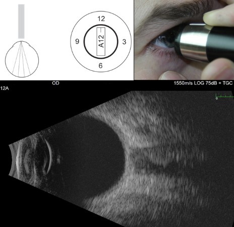
Figure 9.10.1
Axial B-scan
Axial scans pass through the pupil and lens of the eye. When tilted slightly nasal, the optic nerve will be seen. Document the scan by the type (e.g. axial) and the direction (in clock hours, in this case 12 because the marker is pointing superiorly) that the marker on the probe points to.
2. Transverse (T)
Transverse scans are performed with the patient looking in the direction of interest. The probe is placed on the opposite side of the globe at the scleral side of the limbus. The mark of the probe is directed parallel to the limbus. This way, images across the globe can be viewed. This can be further delineated by tilting the probe such that anterior (A), Equatorial (E) or Posterior (P) segments of the globe are scanned.
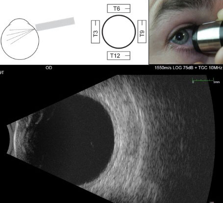
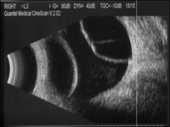
Figure 9.10.2
Transverse B-scan
In a 9T scan, the probe is held on the nasal side of the right eye pointing towards the temporal (9 o’clock) meridian. The marker on the probe is directed parallel to the limbus and by convention is held pointing superiorly. This means that the top of the image is the superior (and in this case temporal) retina.
3. Longitudinal (L)
Longitudinal scans are performed with the patient looking in the direction of interest. The probe is placed on the opposite side of the globe at the scleral side of the limbus. The mark of the probe is directed towards the centre of the cornea (perpendicular to the limbus). This way, the ora serrata is shown at the top of the image and the posterior pole with optic nerve at the bottom. Longitudinal scans are useful in identifying very anterior lesions.
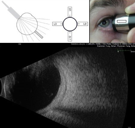
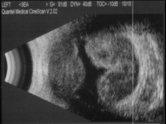
Figure 9.10.3
Longitudinal B-scan
In a 9L scan, the probe is held on the nasal side of the right eye pointing towards the temporal (9 o’clock) meridian. The marker on the probe is directed perpendicular to the limbus. Longitudinal scans visualise from anteriorly (at the top of the image) to posteriorly (at the bottom of the image). The optic nerve is usually seen at the bottom of the image.
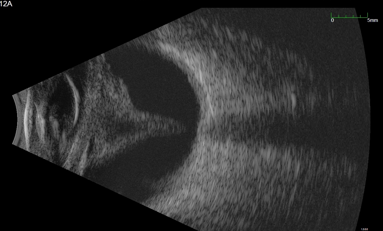
NB: This patient has abnormally thick sclera/choroid and fluid demonstrated posteriorly. This is called the T-sign and is seen in posterior scleritis.
Screening
When there is no view of the posterior segment (such as when there is a dense cataract or vitreous haemorrhage), perform 9 “screening” scans:
- Axial 12
- Transverse 12, 3, 6, 9
- Longitudinal 12, 3, 6, 9
Reading Scans
Describe:
- Location (as documented above)
- Darkness/lightness (echolucent/echodense)
- Shape
- Thickness
- This is especially useful when measuring choroidal tumours. Thickness can be measured by simultaneously displaying the B- and A-scans, with the A-scan vector “cutting” through the thickest point of the lesion on the B-scan. The thickness is then measured between the peaks of the A-scan, corresponding to the anterior and posterior surfaces of the lesion
- Mobility:
- With the B-scan ultrasound probe in position, the patient can be asked to alter their gaze (left and right or up and down) 90 degrees to the orientation of the probe. This helps identify mobile pathology such as a retinal tears, detachment or blood. After-movement refers continuing movement of tissues even after the eye has stopped (due to momentum)
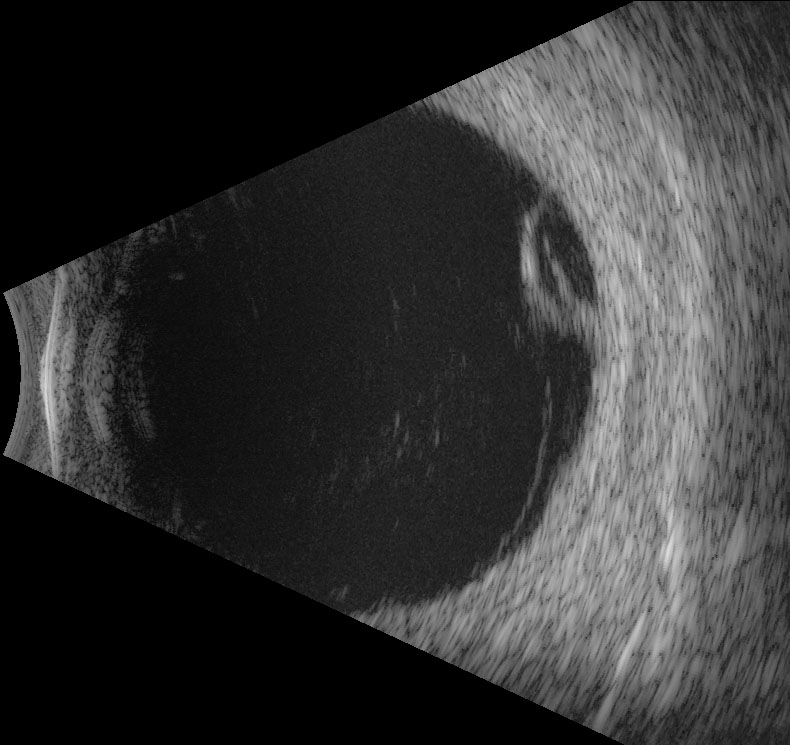
- Figure 9.10.4: B-scan of vitreous haemorrhage secondary to retinal tear
- Figure 9.10.5: B-scan of a funnel retinal detachment
- Figure 9.10.6: B-scan of Pars Plana Cyst
- Figure 9.10.7: B-scan of choroidal effusion
- Figure 9.10.8: B-scan of suprachoroidal haemorrhage
- Figure 9.10.9: Simultaneous B-scan and A-scan of a choroidal melanoma
- Figure 9.10.10: B-scan of choroidal haemangioma
- Figure 9.10.11: B-scan of choroidal lymphoma
- Figure 9.10.12: B-scan of posterior scleritis
- Figure 9.10.13: B-scan of a dropped nucleus from complicated cataract surgery
- Figure 9.10.14: UBM of an iris cyst
- Figure 9.10.15: UBM of uveal effusion syndrome
- Figure 9.10.16: Anterior segment photograph of uveal effusion syndrome
- Figure 9.10.17: Wide-field fundus photograph of uveal effusion syndrome
Common Findings Include:
1. Shadowing of the Optic Nerve
- Finding the optic nerve first often helps to “orient” the examiner. This will be seen in axial scans by tiling the probe slightly nasal and at the bottom of longitudinal scans.
2. Vitreous Opacities/Haemorrhage
- Diffuse echo-opacities that are highly mobile with after-movements. High gain may be required to view mild vitreous haemorrhages.
3. Retinal Detachment
- Highly reflective interface (it should be viewed in at least two planes to prove this), usually attaching to the eye wall at a shallow angle. Mobile with some after-movement (although tractional detachments may have limited mobility). Even in a total retinal detachment the retina always remains attached at the optic disc
4. Posterior vitreous detachment
- Thinner interface, less reflective, greater after-movement than retinal detachments
5. Retinoschisis
- Peripheral (not involving the posterior pole), dome shaped interface that is thinner and less mobile than a retinal detachment
6. Pars Plana Cyst
- Thin, peripheral, dome shaped elevation with echolucent centre
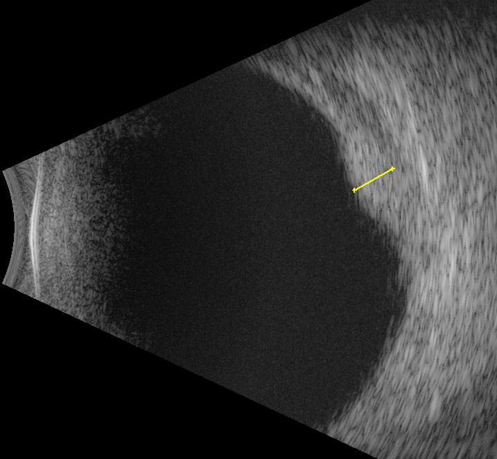
7. Choroidal Detachment (Effusion, Haemorrhage)
- Peripheral (not involving the posterior pole), dome shaped interface that is thicker and less mobile than a retinal detachment. In a choroidal effusion the contents are echolucent; in a choroidal haemorrhage the contents are echo-opaque
8. Choroidal Tumours
A. Choroidal Melanoma
- Low internal reflectivity. This occurs because the tumour cells are relatively homogenous and densely packed, so the number of reflective surfaces is minimal.
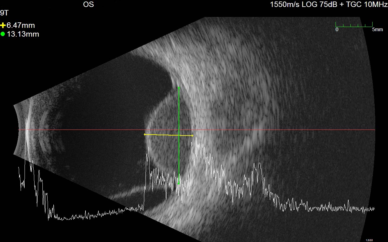
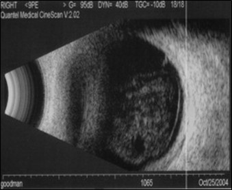
Figure 9.10.9
Simultaneous B-scan and A-scan of a choroidal melanoma
Note the echolucency on the B-scan, typical of a choroidal melanoma, as well as the inferior serous retinal detachment. The A-scan demonstrates a high initial spike and low internal reflectivity. The thickness of the tumour is measured between the “spikes” of the A-scan after placing the vector at the thickest point on the B-scan.
All rights reserved. No part of this publication which includes all images and diagrams may be reproduced, distributed, or transmitted in any form or by any means, including photocopying, recording, or other electronic or mechanical methods, without the prior written permission of the authors, except in the case of brief quotations embodied in critical reviews and certain other noncommercial uses permitted by copyright law.

Vitreoretinal Surgery Online
This open-source textbook provides step-by-step instructions for the full spectrum of vitreoretinal surgical procedures. An international collaboration from over 90 authors worldwide, this text is rich in high quality videos and illustrations.